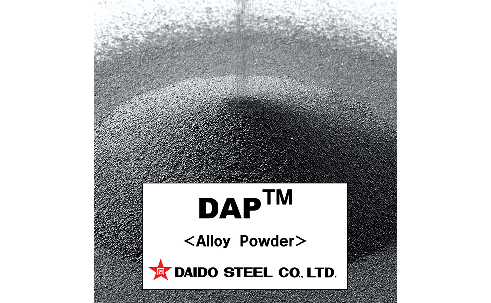
DAPTM-AM Series - Metal Powders for 3D Printing -
- Metal powders for 3D printing by SLM
High Thermal Conductivity Powders for Molds DAPTM-AM HTC45 and DAPTM-AM HTC40
DAPTM-AM HTC45 and DAPTM-AM HTC40 have been developed by adjusting chemical composition of steel suitable for additive manufacturing by SLM.
DAPTM-AM HTC series have excellent flowability and physical characteristics suitable for additive manufacturing.
Characteristics
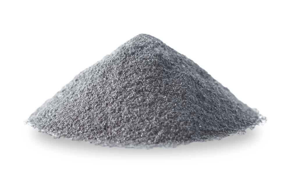
- DAPTM-AM HTC45 and DAPTM-AM HTC40 are spherical powders produced by gas atomization and have low oxygen content and high flowability.
- Cracking during 3D printing can be reduced as these powders have been developed by modifying chemical composition*1.
- The cooling effect of mold can be enhanced by increasing thermal conductivity.
In addition, thermal stress can also be reduced, which prevents heat checking, and cracks originating from cooling holes.
*1 A base plate temperature of 200°C is recommended to prevent cracking during 3D printing.
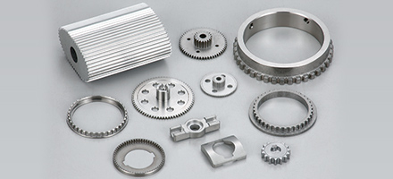
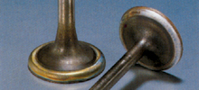
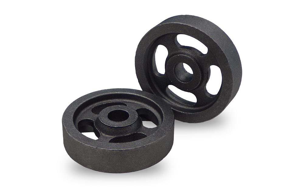
Major applications
- Pins and inserts etc. with cooling holes
Typical chemical composition and hardness range
| DAPTM-AM series | Equivalent steel grade |
Hardness (HRC) |
Typical chemical composition (mass%) | Application | ||||
| C | Si | Cr | Mo | V | ||||
| DAPTM-AM HTC45 | SKD61 type Die steel | 40~50 | 0.23 | 0.1 | 5 | 1.2 | 0.4 | Die-casting molds |
| DAPTM-AM HTC40 | SKD61 type Die steel | 35~45 | 0.13 | 0.1 | 5 | 1.2 | 0.4 | Die-casting molds Plastic injection molds |
DAP and HTC are trademarks or registered trademarks of Daido Steel Co., Ltd.
Particle size
| Particle size (µm) |
| -53/+25 |
Characteristics
Hardness is reduced to a practical level, and cracks during 3D printing are prevented. Hardness can be adjusted by tempering*2 after 3D printing.
(*2 Tempering at 550°C or higher is recommended to release residual stress.)
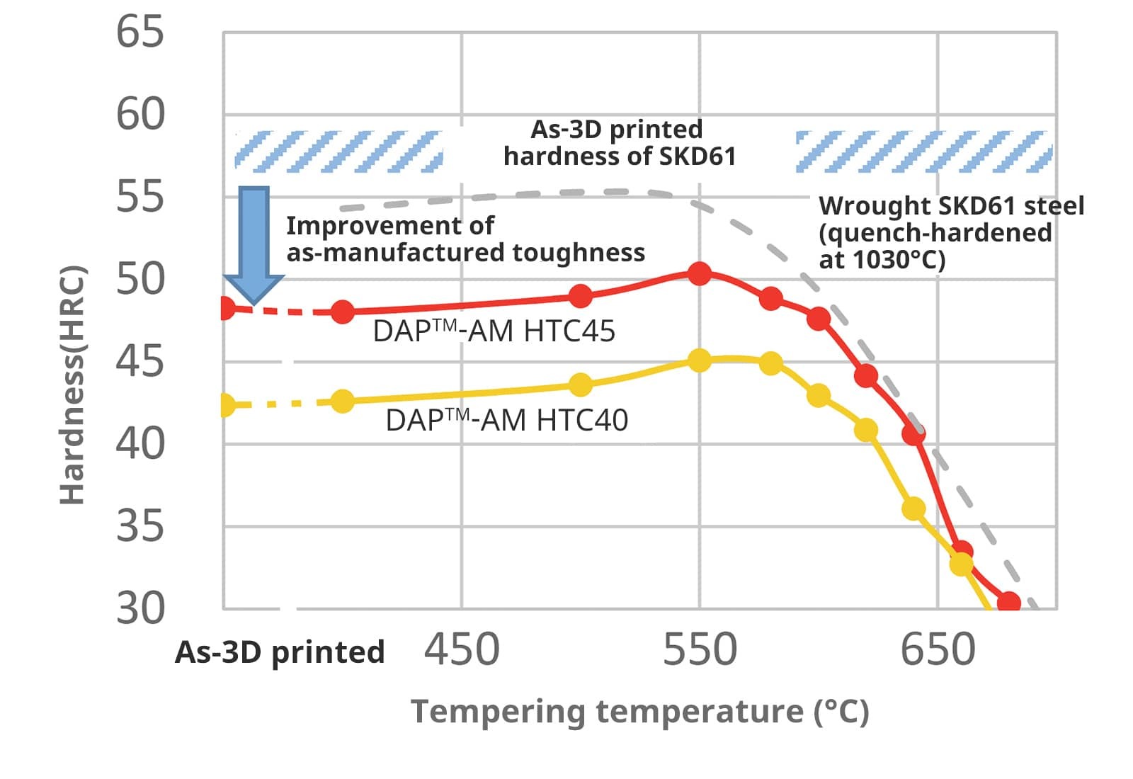
Fig. 1 Correlation of the hardness between as-3D printed and tempered after 3D printing.
(Tempering [T°C × 1h] 2 times, base plate temperature 200°C)
DAPTM-AM HTC series can cool molds efficiently by improving thermal conductivity. They can also reduce thermal stress and prevent heat checking and cracks originating from cooling holes.
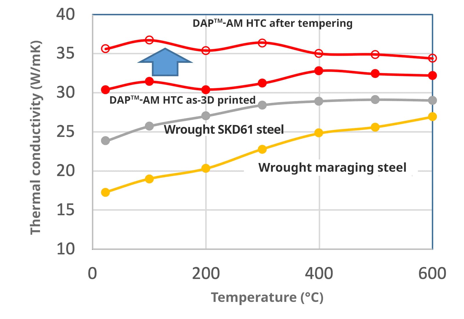
Fig. 2 Comparison of thermal conductivity.
(Laser flash method)
The tensile strength and 0.2% proof stress are equivalent to wrought SKD61 type steel with the same hardness as DAPTM-AM HTC.
The impact value is higher than that of wrought SKD61 type steel with the same hardness as DAPTM-AM HTC due to low carbonization.
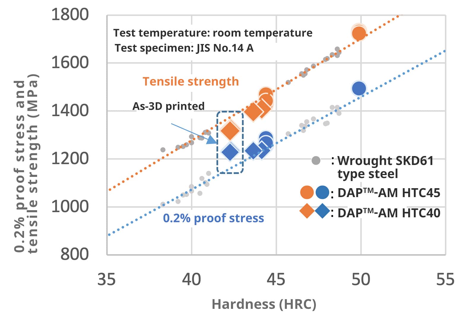
Fig. 3 Relationship between hardness, 0.2% proof stress,
and tensile strength of DAPTM-AM HTC*3.
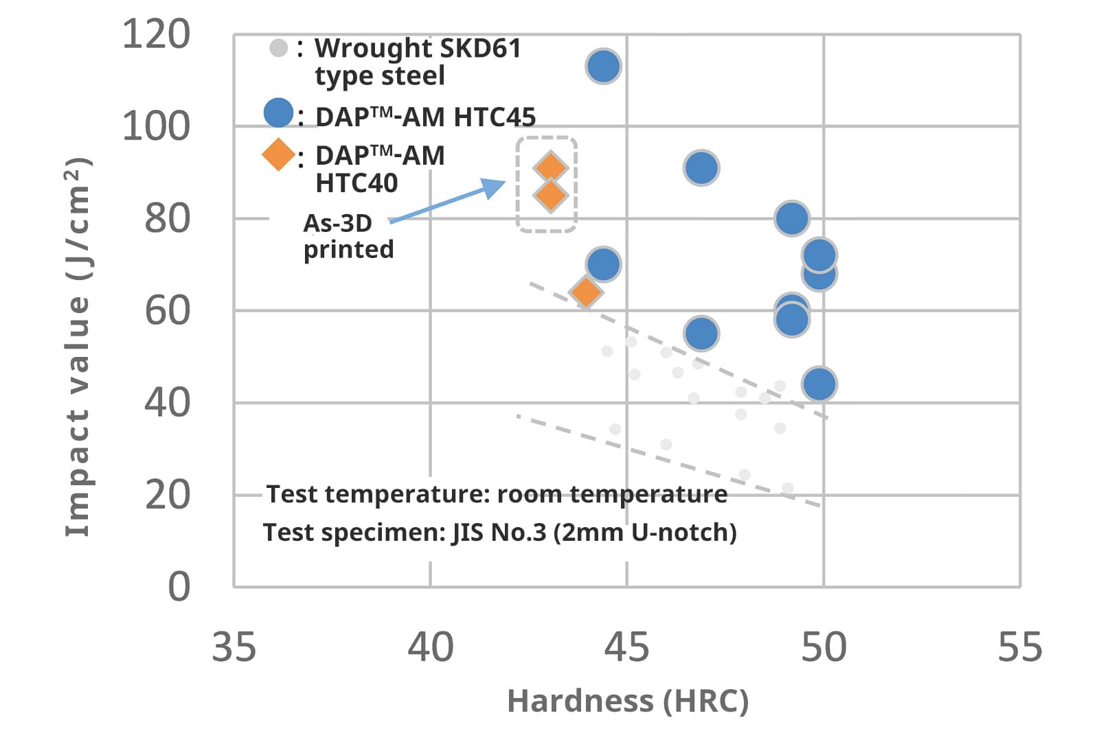
Fig. 4 Relationship between hardness and impact value of DAPTM-AM HTC.
Fatigue strength of 3D printed specimens are lower than that of wrought steel with the same hardness due to defects formed during 3D printing. It is possible to improve the fatigue strength by optimizing the 3D printing parameters.

Fig. 5 Fatigue strength and typical fatigue fracture surface of DAPTM-AM HTC*3.
| Calculation item | Calculation results | Expected improvement |
| Decrease in maximum temperature of the mold surface (point A) | -17℃ | Restrain mold from seizing and improving cycle time |
| Stress amplitude on the surface of cooling hole (point B) | -10% | Prolonging die life of crack initiation from cooling hole |
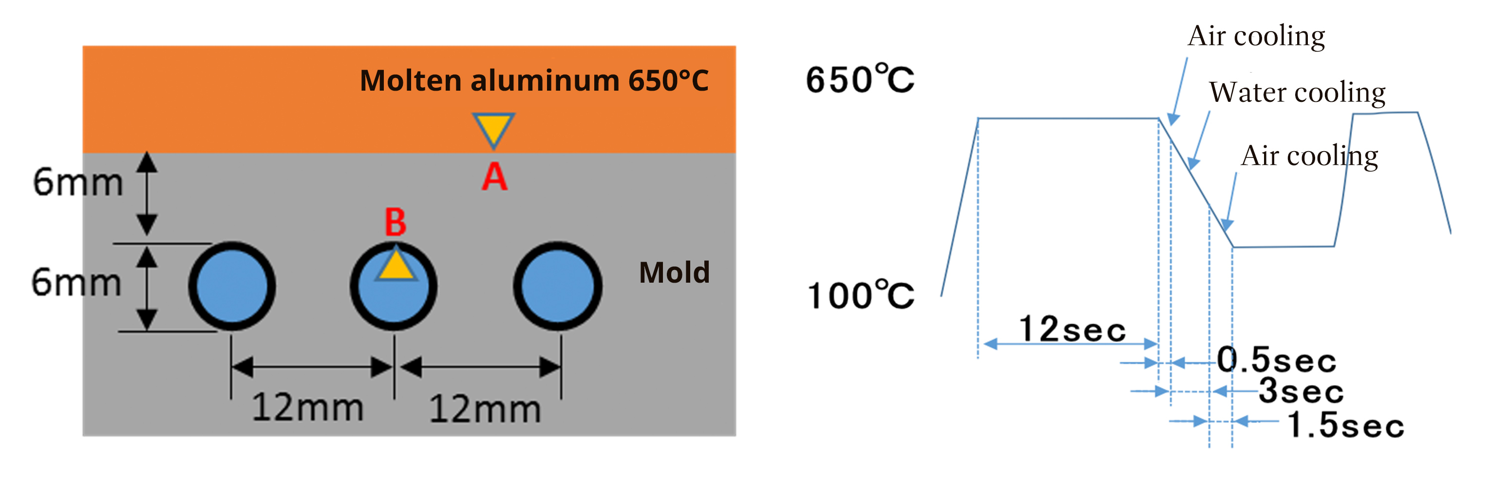
Fig. 6 FEM analysis model and thermal history.
The improved thermal conductivity lowers the temperature of the mold surface and further reduces the seizure of die-cast molds.The stress on the surface of cooling holes also decreases, which can prolong mold life preventing cracking from the cooling hole.
DAPTM-AM HTC has high thermal conductivity, which results in lower thermal stress and reduced heat checking in comparison to SKD61 under the same thermal history.

Fig. 7 Heat checking test results*3.
(Notch shape: R=6mm, depth 1mm)
*3 All the test results of tensile strength, Charpy impact value, fatigue strength, and heat check are carried out with the material 3D printed in accordance with the original recipe of Mitsubishi Corporation Technos.
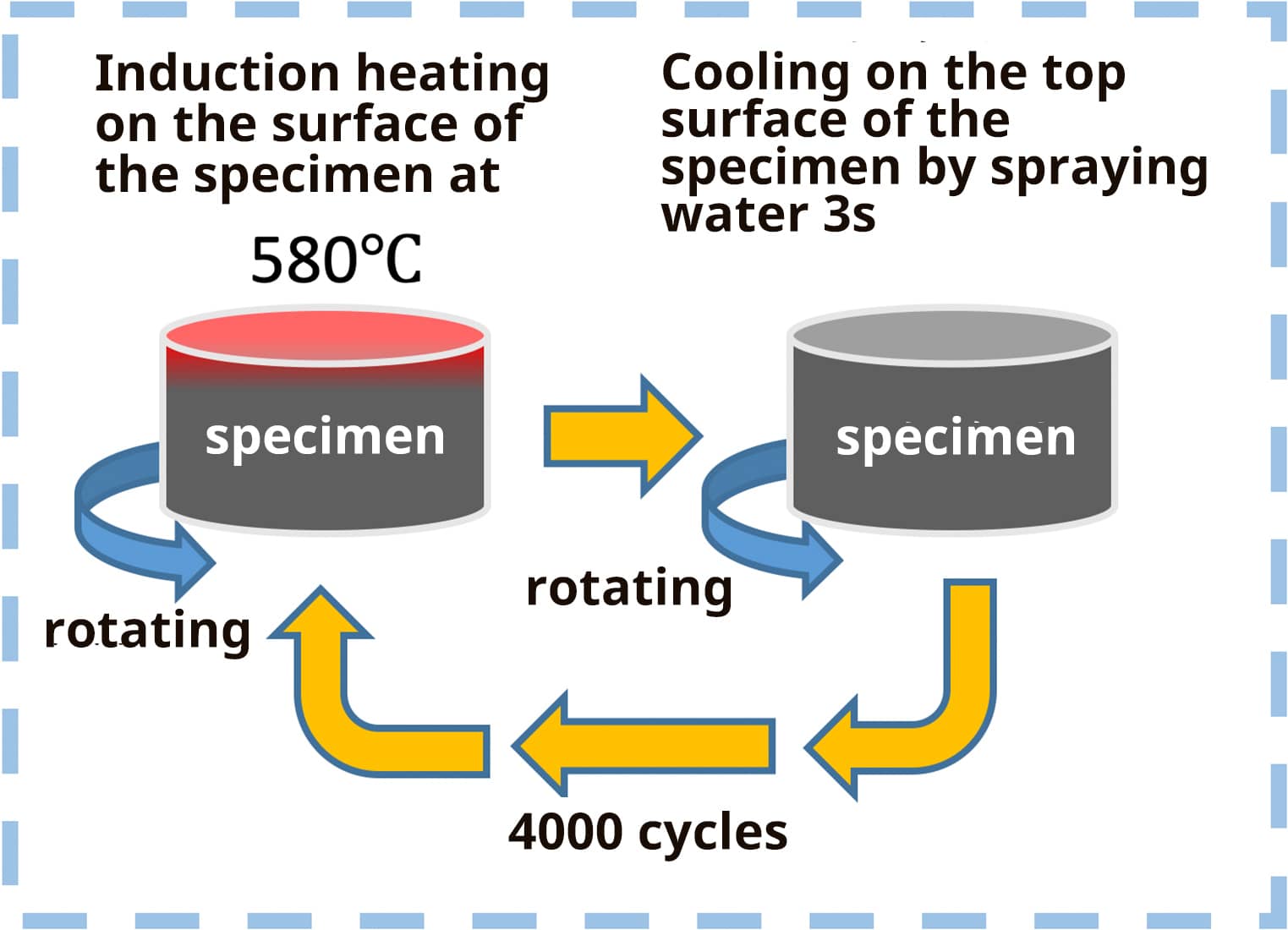
Fig. 8 Overview of heat checking test.
3D printing process parameters
The data shown in Table 2 are 3D printing process parameters for GE Additive’s Concept Laser M2 machine.
When using other equipments, please refer to the table for optimizing conditions.
Please feel free to ask our Metal Powder Department about the process parameters.
| Part | Laser power (W) | Laser spot diameter (µm) | Scanning speed (mm/s) | Hatching distance (mm) | Layer thickness (μm) | |
| Product | Inside | 300 | 180 | 600 | 0.13 | 50 |
| Contour*5 | 150 | 100 | 300 | ― | 50 | |
| Downskin*6 | Inside | 380 | 180 | 950 | 0.13 | 50 |
| Contour*5 | 125 | 100 | 750 | ― | 50 | |
| Supporting part | 150 | 100 | 700 | ― | 50 | |
The recommended laser scanning pattern is a checker-board type and the recommended base plate temperature is 200°C.
*4 Recommendations are for reference only and do not guarantee the aforementioned quality of mechanical properties and fatigue strength, etc.
*5 Process parameters for forming outline part
2 times irradiating laser on the contour part (2nd time is shifted 70 μm inward from 1st time) can reduce defects in the border between contour part and inside part.
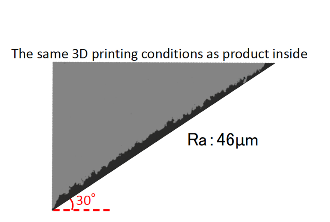
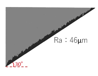
*6 Since the surface of the downskin part tends to be rough, the surface roughness can be reduced by applying the specific molding parameters shown in Table 2.
(Note : Downskin contour area should be irradiated by a single laser.)
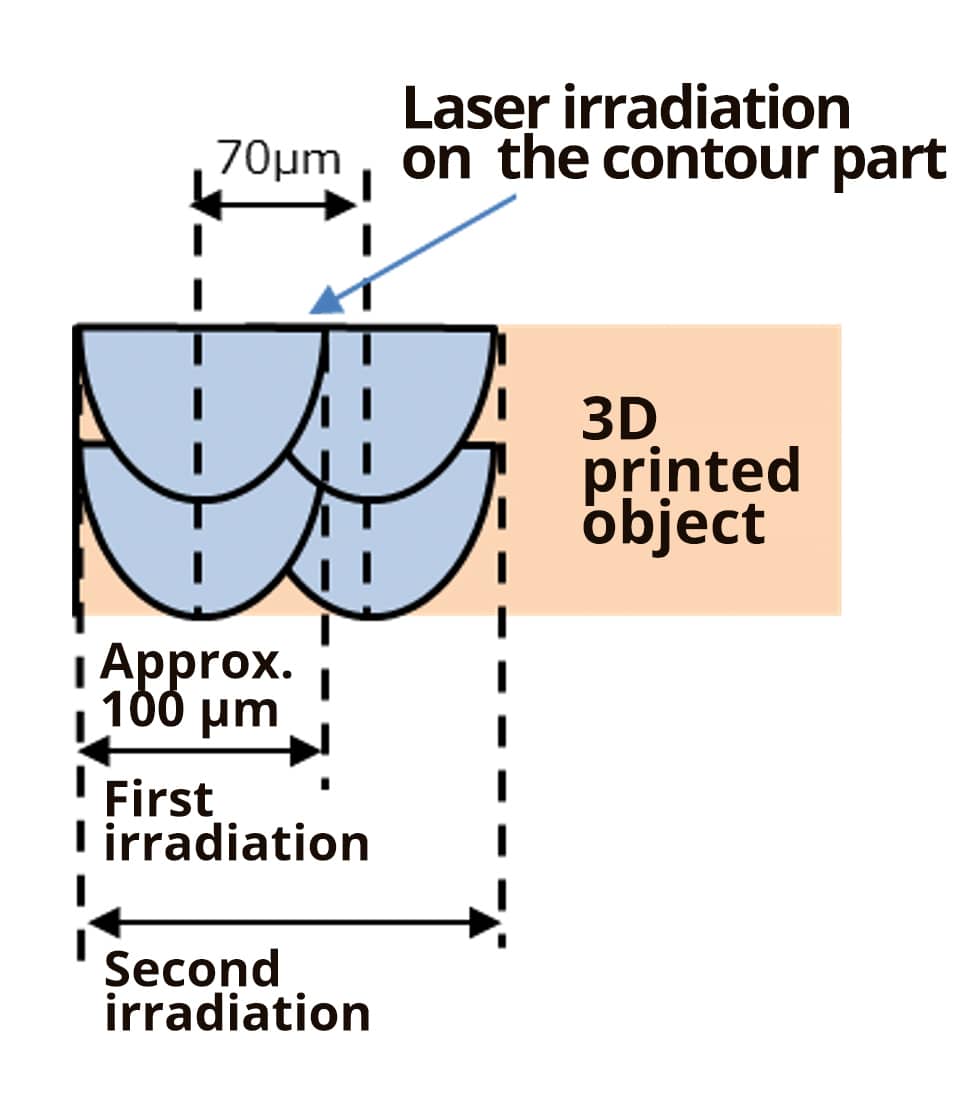
Fig. 9 Image of laser irradiation (2 times) to form the outline part.
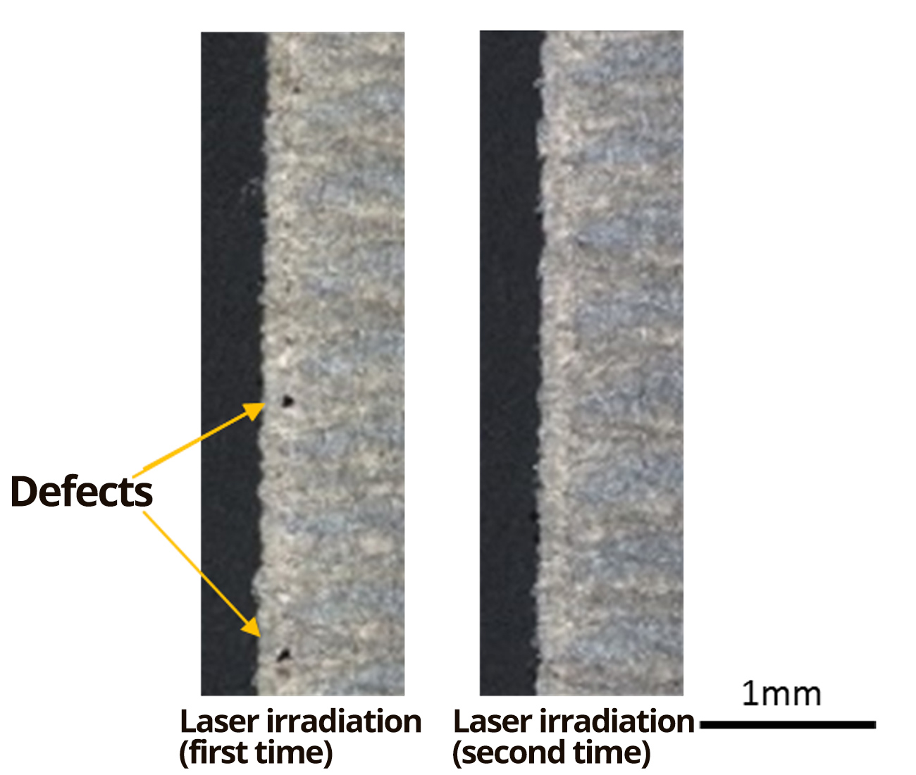
Fig. 10 Defects in the border between outer part and inside part.
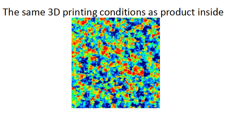
The same 3D printing conditions as product inside
Recommended conditions
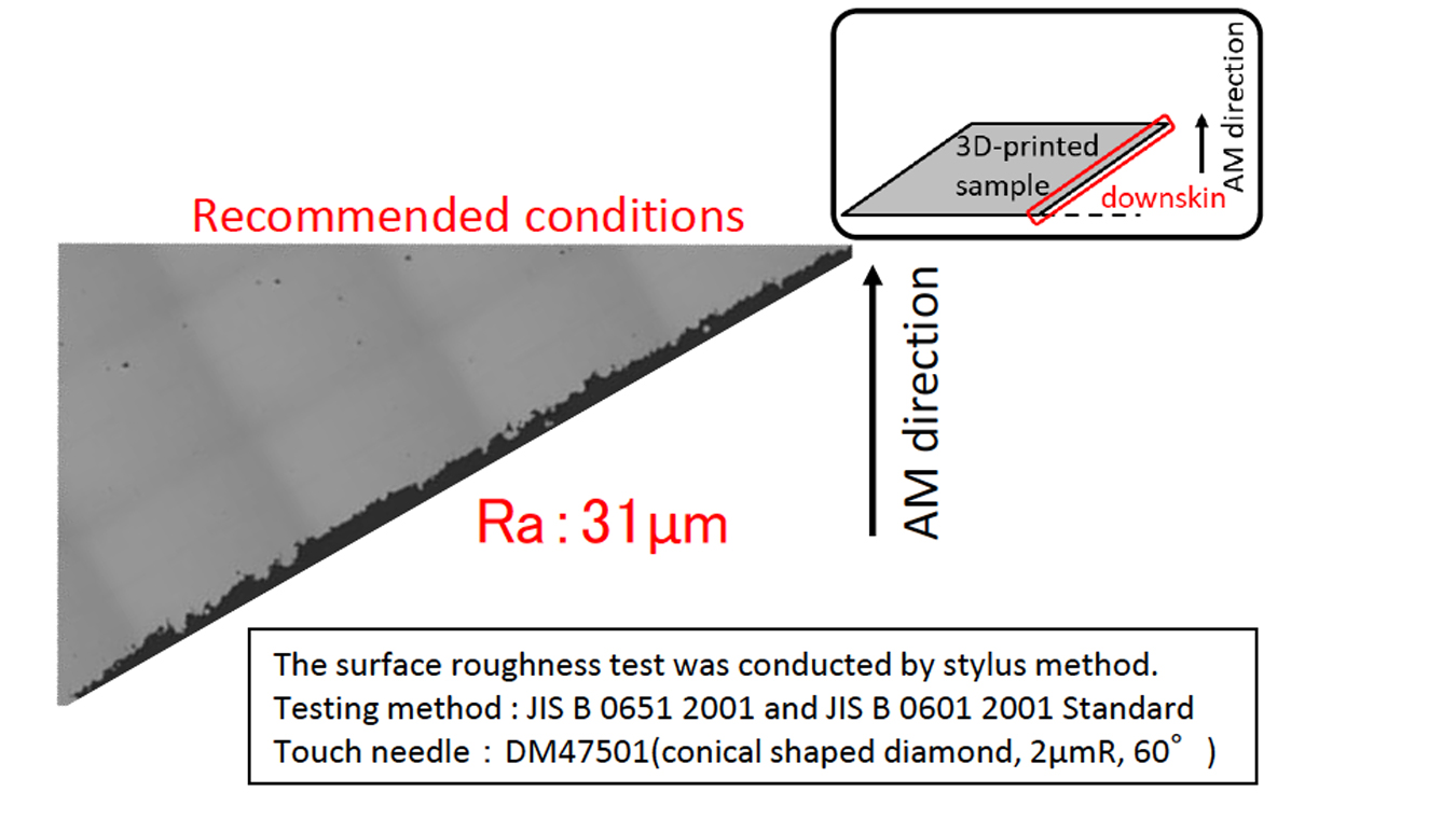
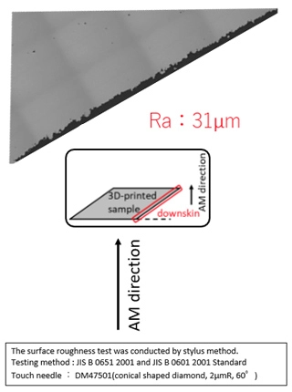
Fig. 11 The comparison of cross-sectional roughness of the downskin part.(the angle of the downskin:30°)
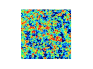
The same 3D printing conditions as product inside
Recommended conditions
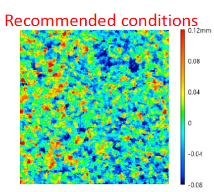
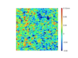
Fig. 12 The comparison of the surface roughness of the downskin area by 3D measurement.
Mold manufacturing process using DAPTM-AM HTC
DAPTM-AM HTC can be quench-hardened during 3D printing.
In order to prevent cracking and deterioration of toughness caused by secondary hardening during tempering, the surface of 3D printed product should be smoothed, and then tempering should be carried out to adjust the hardness or stress-relief annealing is performed.
Distortion after removal from the base plate is reduced if heat treating is performed without detaching it form the base plate.

Fig. 13 Typical mold manufacturing process using DAPTM-AM HTC.
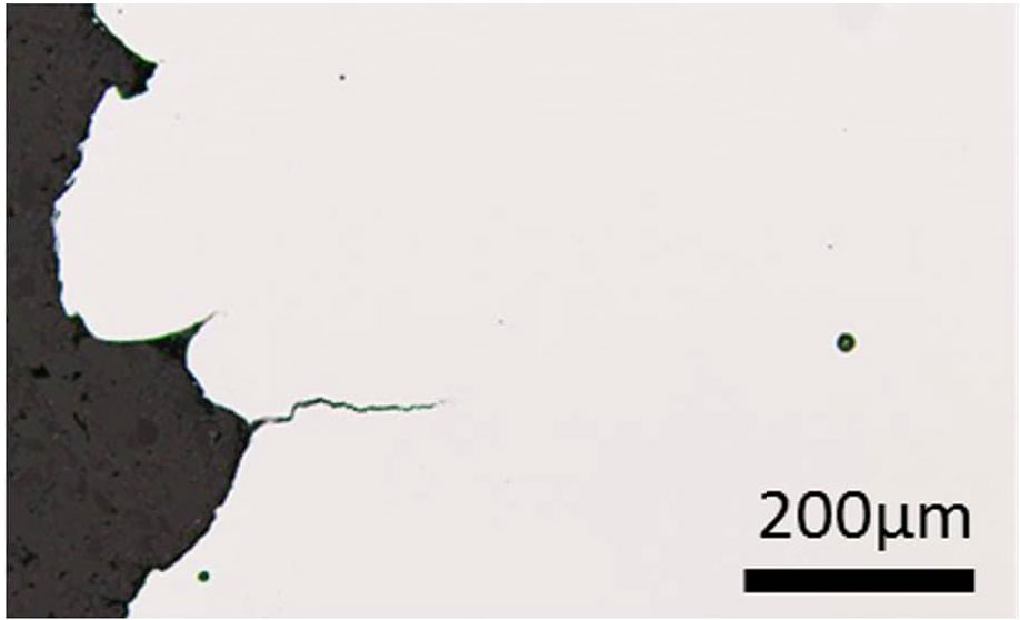
Fig. 14 Initial cracks caused by tempering after 3D printing.
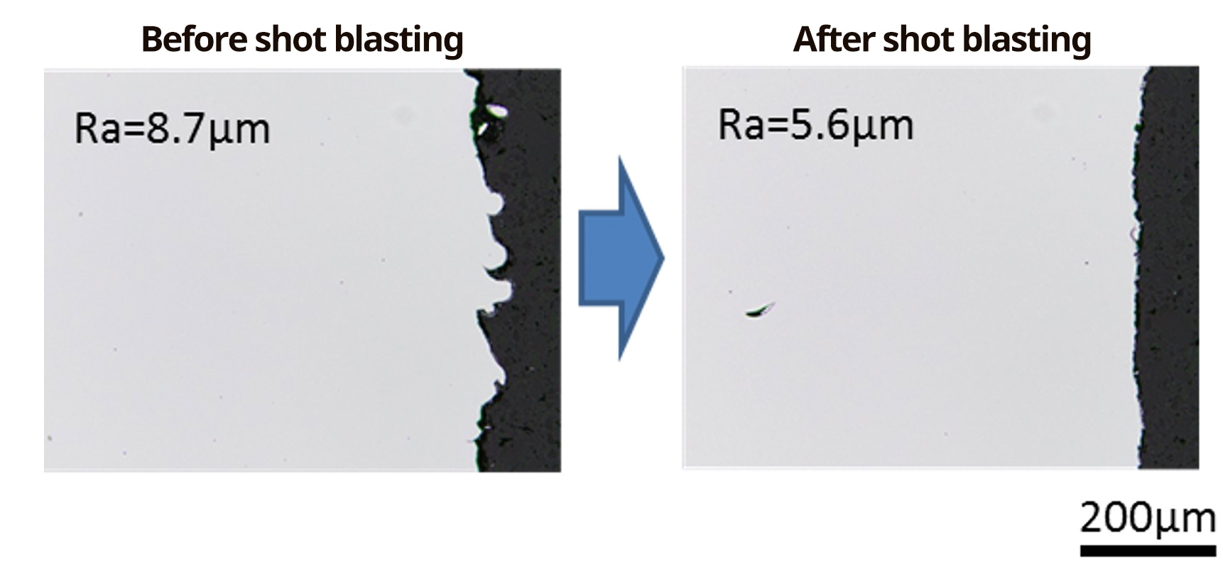
Fig. 15 Mold surface before and after shot blasting.
Cracking of 3D printed object is caused by the surface roughness perpendicular to the base plate. Smoothing the rough surface reduces the risk of cracking.

Smoothing the surface perpendicular to the base plate by shot blasting.
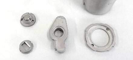
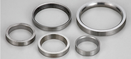
3D printed models
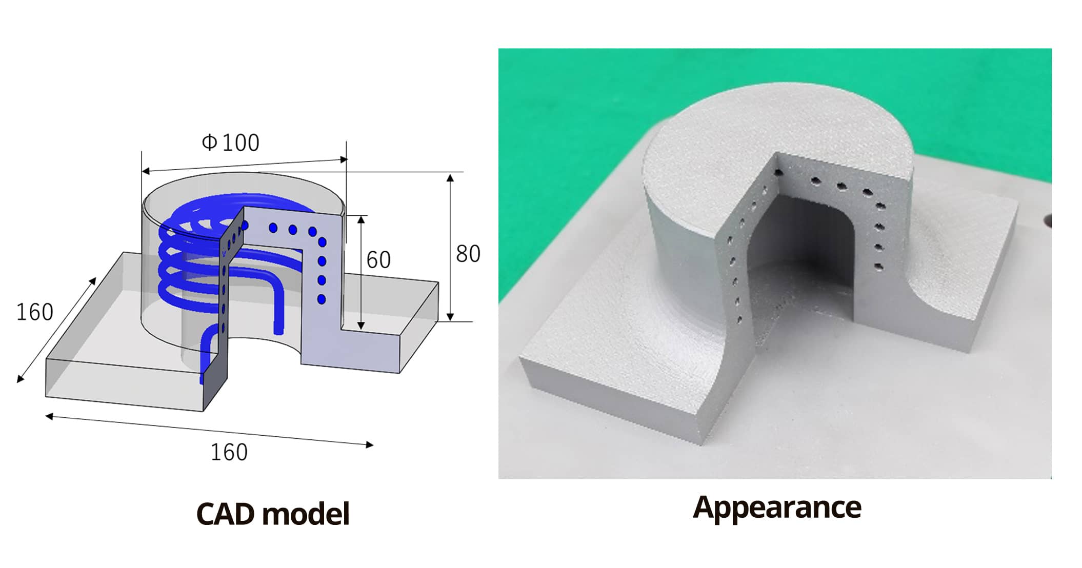
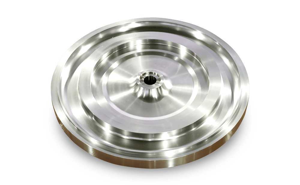
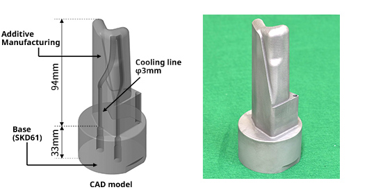
Fig. 16 3D model of a manufactured mold using DAPTM-AM HTC40.
(Manufactured with GE Additive’s Concept Laser M2 machine)
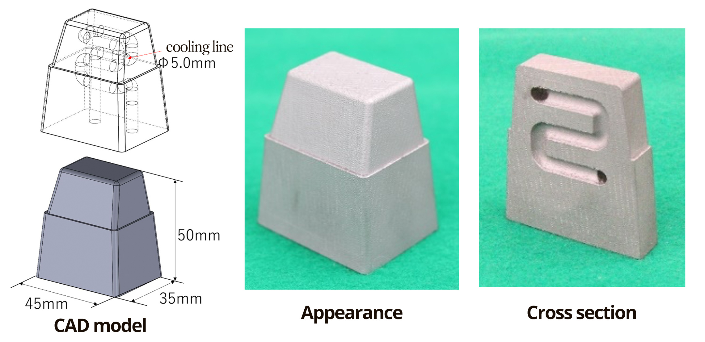
Fig. 17 3D model of a manufactured mold using DAPTM-AM HTC45.
(Manufactured with GE Additive’s Concept Laser M2 machine)
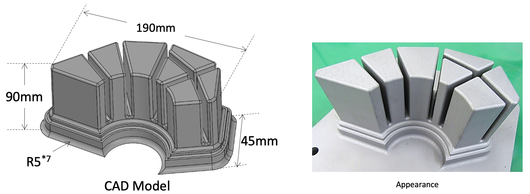
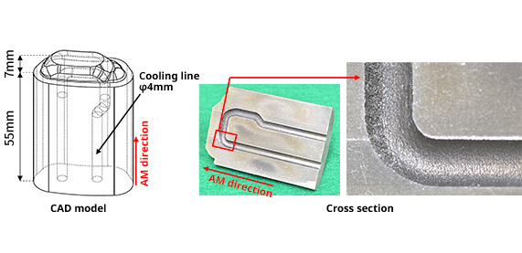
Fig.16 3D model of a large sample using DAPTM-AM HTC45.
(Manufactured with GE Additive’s Concept Laser M2 machine)
*7 To prevent cracking, the boundary between the base plate and the sample is 3D printed with R5.
Examples of 3D printing using precision metal 3D printer OPM250L of Sodick Co., Ltd.
| Technical data | Applied to cool a die casting mold (1,105KB) |
| Printer |
Precision metal 3D printer OPM250L
(Click here to Sodick Co., Ltd.'s page) |
| Size (mm) | 70 × 80 × 90 |
| Material | DAPTM-AM HTC45, Base S50C |
Examples of 3D printing using 3D printer M2 of Nihonseiki Co., LTD.
Example 1
| Printer |
Nihonseiki Co., LTD.
(Click here to the website.) |
| Printer | 3D printer M2 of Concept Laser GmbH |
| Size (mm) | φ54×127(Example 1) 45×16×62(Example 2) |
| Material | DAPTM-AM HTC45 |
Example 2
Technical data
Disclaimer and copyright
The figures in this document are typical values based on the results of our tests and there is no guarantee that the figures presented will be achieved when the products are used.
The information in this document is subject to change without notice.
Please contact us for the latest information.Any unauthorized distribution or reproduction of the content of this document is prohibited.
DAP and HTC are trademarks or registered trademarks of Daido Steel Co., Ltd.